|
|
|
|
|
|
|
|
|
|
|
|
|
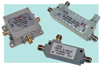
| Directional Couplers (Unidirectional) | |
|
|
|
|
- Specifications are
subject to change without notice - Click on the product model number for Specifications-Sheet in PDF - Click on " |
|
|
Sales/Technical Contact Email: Sales@UMCC111.com |
|
RF Circuit |
|
|
|
Low Frequency Couplers (Lumped
Element) 10 KHz - 2400 MHz |
|||||||||||
| 10 KHz - 30 MHz | |||||||||||
| Model
No. |
Freq. Range |
Coupling (dB) Max (1,2) |
Coupling
Flatness (dB) Max |
Directivity (dB) Min |
Line Loss
Total (dB) Max (3) |
VSWR Max |
Power Handling CW/Peak |
Outline Drawing |
|||
|
DC-003S-10S Slimline Pkg. with SMA(f) |
10KHz - 30MHz |
10 -/+ 0.5 | -/+ 0.5 | 22 | 1.0 | 10-20
KHz |
0.02-30 MHz |
1 W |
Fig.5 Slimline Pkg. with SMA(f) |
||
| 1.65:1 | 1.35:1 | ||||||||||
|
DC-0030-10S with SMA(f) DC-0030-10B with BNC(f) DC-0030-10N with N(f) |
10KHz - 30MHz |
10 -/+ 0.5 | -/+ 0.5 | 22 | 1.0 | 10-20
KHz |
0.02-30 MHz |
1 W |
Fig.6 Universal Pkg. |
||
| 1.65:1 |
1.35:1 |
||||||||||
|
DC-003S-20S Slimline Pkg. with SMA(f) |
10KHz - 30MHz |
20 -/+ 1 | -/+ 0.5 | 19 | 1.3 | 1.35:1 | 2 W |
Fig.5 Slimline Pkg. with SMA(f) |
|||
|
DC-0030-20S with SMA(f) DC-0030-20B with BNC(f) DC-0030-20N with N(f) |
10KHz - 30MHz |
20 -/+ 1 | -/+ 0.5 | 19 | 1.3 | 1.35:1 | 2 W |
Fig.6 Universal Pkg. |
|||
|
DC-003S-30S Slimline Pkg. with SMA(f) |
10KHz - 30MHz |
30 -/+ 1 | -/+ 0.5 | 19 | 1.3 | 1.35:1 | 2 W |
Fig.5 Slimline Pkg. with SMA(f) |
|||
|
DC-0030-30S with SMA(f) DC-0030-30B with BNC(f) DC-0030-30N with N(f) |
10KHz - 30MHz |
30 -/+ 1 | -/+ 0.5 | 19 | 1.3 | 1.35:1 | 2 W |
Fig.6 Universal Pkg. |
|||
| 1 - 500 MHz | |||||||||||
| Model No. | Freq. Range |
Coupling (dB) Max (1,2) |
Coupling
Flatness (dB) Max |
Directivity (dB) Min |
Line Loss
Total (dB) Max (3) |
VSWR Max |
Power Handling CW/Peak |
Outline Drawing |
|||
|
DC-050S-11S Slimline Pkg. with SMA(f) |
1-500
MHz |
11 -/+ 1 | -/+ 0.6 | 1-100 MHz |
100-500 MHz |
1-100 MHz |
100-500 MHz |
1-2 MHz |
2-500 MHz |
1 W |
Fig.5 Slimline Pkg. with SMA(f) |
| 35 | 25 | 1.4 | 1.9 | 1.5:1 | 1.35:1 | ||||||
|
DC-0500-11S with SMA(f) DC-0500-11B with BNC(f) DC-0500-11N with N(f) |
1-500
MHz |
11 -/+ 1 |
-/+ 0.6 |
1-100 MHz |
100-500 MHz |
1-100 MHz |
100-500 MHz |
1-2 MHz |
2-500 MHz |
1 W |
Fig.6 Universal Pkg. |
| 35 | 25 | 1.4 | 1.9 | 1.5:1 | 1.35:1 | ||||||
|
DC-050S-20S Slimline Pkg. with SMA(f) |
1-500
MHz |
20 -/+ 1 | -/+ 0.7 | 22 | 0.9 | 1.35:1 | 2 W |
Fig.5 Slimline Pkg. with SMA(f) |
|||
|
DC-0500-20S with SMA(f) DC-0500-20B with BNC(f) DC-0500-20N with N(f) |
1-500
MHz |
20 -/+ 1 | -/+ 1.0 | 1-100 MHz |
100-500 MHz |
0.9 | 1-2 MHz |
2-500 MHz |
2 W |
Fig.6 Universal Pkg. |
|
| 25 | 20 | 1.5:1 | 1.35:1 | ||||||||
|
DC-050S-30S Slimline Pkg. with SMA(f) |
1-500
MHz |
30 -/+ 1.5 | -/+ 0.9 | 1-100 MHz |
100-500 MHz |
0.8 | 1-2 MHz |
2-500 MHz |
2 W |
Fig.5 Slimline Pkg. with SMA(f) |
|
| 25 | 20 | 1.5:1 | 1.35:1 | ||||||||
|
DC-0500-30S with SMA(f) DC-0500-30B with BNC(f) DC-0500-30N with N(f) |
1-500
MHz |
30 -/+ 1.5 | -/+ 0.9 | 1-100 MHz |
100-500 MHz |
0.8 | 1-2 MHz |
2-500 MHz |
2 W |
Fig.6 Universal Pkg. |
|
| 25 | 20 | 1.5:1 | 1.35:1 | ||||||||
| 10 - 1000 MHz | |||||||||||
| Model No. | Freq. Range |
Coupling (dB) Max (1,2) |
Coupling
Flatness (dB) Max |
Directivity (dB) Min |
Line Loss
Total (dB) Max (3) |
VSWR Max |
Power Handling CW/Peak |
Outline Drawing |
|||
|
DC-100S-11S Slimline Pkg. with SMA(f) |
10-1000 MHz |
11 -/+ 1 | -/+ 0.8 | 18 | 1.7 | 1.5:1 | 1 W |
Fig.5 Slimline Pkg. with SMA(f) |
|||
|
DC-1000-11S with SMA(f) DC-1000-11B with BNC(f) DC-1000-11N with N(f) |
10-1000 MHz |
11 -/+ 1 | -/+ 0.8 | 18 | 1.7 | 1.5:1 | 1 W |
Fig.6 Universal Pkg. |
|||
|
DC-100S-20S Slimline Pkg. with SMA(f) |
10-1000 MHz |
20 -/+ 1 | -/+ 0.9 | 18 |
10-500 MHz |
500-1000 MHz |
10-20 MHz |
20-1000 MHz |
2 W |
Fig.5 Slimline Pkg. with SMA(f) |
|
| 0.5 | 0.9 | 1.8:1 | 1.35:1 | ||||||||
|
DC-1000-20S with SMA(f) DC-1000-20B with BNC(f) DC-1000-20N with N(f) |
10-1000 MHz |
20 -/+ 1 | -/+ 0.9 | 18 |
10-500 MHz |
500-1000 MHz |
10-20 MHz |
20-1000 MHz |
2 W |
Fig.6 Universal Pkg. |
|
| 0.5 | 0.9 | 1.8:1 | 1.35:1 | ||||||||
|
DC-100S-30S Slimline Pkg. with SMA(f) |
10-1000 MHz |
30 -/+ 1.5 | -/+ 0.9 | 18 | 10-500 MHz |
500-1000 MHz |
10-20 MHz |
20-1000 MHz |
2 W |
Fig.5 Slimline Pkg. with SMA(f) |
|
| 0.5 | 0.9 | 1.8:1 | 1.35:1 | ||||||||
|
DC-1000-30S with SMA(f) DC-1000-30B with BNC(f) DC-1000-30N with N(f) |
10-1000 MHz |
30 -/+ 1.5 | -/+ 0.9 | 18 | 10-500 MHz |
500-1000 MHz |
10-20 MHz |
20-1000 MHz |
2 W |
Fig.6 Universal Pkg. |
|
| 0.5 | 0.9 | 1.8:1 | 1.35:1 | ||||||||
| 10 - 2400 MHz | |||||||||||
| Model No. | Freq. Range |
Coupling (dB) Max (1,2) |
Coupling
Flatness (dB) Max |
Directivity (dB) Min |
Line Loss
Total (dB) Max (3) |
VSWR Max |
Power Handling CW/Peak |
Outline Drawing |
|||
|
DC-2000-10S |
10-2400
MHz |
10 -/+ 1 | -/+ 0.5 | 15 | 3.4 | 1.25:1 | 1 W | Fig.4 | |||
|
DC-2000-20S |
10-2000
MHz |
20 -/+ 1.5 | -/+ 1.5 | 16 | 1.3 | 1.30:1 | 1 W | ||||
| DC-2000-30S | 30 -/+ 1.5 | -/+ 1.5 | 16 | 1.3 | 1.30:1 | 1 W | |||||
|
1) Coupling is nominal and relative to input power 2) Coupling includes frequency flatness 3) Line Loss includes Insertion and Coupling Losses |
|||||||||||
|
Narrow-Band Directional Couplers ( Stripline ) |
||||||||||
| Model
No. |
Freq. Range |
Coupling (dB) Max (1,2) |
Coupling
Flatness (dB) Max |
Directivity (dB) Min |
Line Loss
Total (dB) Max (3) |
VSWR Max |
Max Power (Cw/Avg) |
Outline Drawing |
||
| LINE | CPL |
Input (W) |
Reflected (W) |
|||||||
|
DC-CH00-6S |
0.9 - 2.1 GHz | 6 -/+ 0.5 | -/+ 0.4 | 28 | 1.60 | 1.20 | 1.20 | 50 | 4 | Fig.1 |
|
DC-CH00-10S |
10 -/+ 0.75 | -/+ 0.3 | 25 | 0.70 | 1.15 | 1.15 | 50 | 10 | ||
| DC-C000-16S | 1 - 2 GHz | 16 -/+ 1 | -/+ 0.4 | 20 | 0.35 | 1.20 | 1.20 | 50 | 25 | |
|
DC-CH00-20S |
0.9 - 2.1 GHz | 20 -/+ 0.75 | -/+ 0.3 | 23 | 0.20 | 1.15 | 1.15 | 50 | 50 | |
|
DC-CH00-30S |
30 -/+ 1 | -/+ 0.3 | 23 | 0.20 | 1.15 | 1.15 | 50 | 50 | ||
| Model# | Frequency Band | Coupling (dB) Max (1,2) |
CPL Flatness
(dB) Max |
Directivity
(dB) Min |
Line Loss
(dB) Max (3) |
VSWR |
Input (W) |
Reflected (W) |
Outline | |
| LINE | CPL | |||||||||
| DC-D000-6S | 2 - 4 GHz | 6 -/+ 0.75 | -/+ 0.4 | 20 | 1.50 | 1.20 | 1.20 | 50 | 4 | Fig.1 |
|
DC-D000-10S |
1.8 - 4.2 GHz | 10 -/+ 1 | -/+ 0.4 | 22 | 0.80 | 1.20 | 1.20 | 50 | 10 | |
| DC-D000-16S | 2 - 4 GHz | 16 -/+ 1 | -/+ 0.4 | 20 | 0.35 | 1.20 | 1.20 | 50 | 25 | |
| DC-D000-20S | 20 -/+ 1 | -/+ 0.4 | 20 | 0.25 | 1.20 | 1.20 | 50 | 50 | ||
| DC-D000-30S | 30 -/+ 1 | -/+ 0.5 | 20 | 0.20 | 1.20 | 1.20 | 50 | 50 | ||
| Model# | Frequency Band | Coupling (dB) Max (1,2) |
CPL Flatness
(dB) Max |
Directivity
(dB) Min |
Line Loss
(dB) Max (3) |
VSWR |
Input (W) |
Reflected (W) |
Outline | |
| LINE | CPL | |||||||||
| DC-H000-6S | 3 - 6 GHz | 6 -/+ 0.75 | -/+ 0.4 | 20 | 1.55 | 1.30 | 1.35 | 50 | 4 | Fig.3 |
| DC-H000-10S | 10 -/+ 1 | -/+ 0.4 | 16 | 0.85 | 1.30 | 1.35 | 50 | 10 | ||
| DC-H000-16S | 16 -/+ 1 | -/+ 0.4 | 16 | 0.40 | 1.30 | 1.30 | 50 | 25 | ||
| DC-H000-20S | 20 -/+ 1 | -/+ 0.4 | 16 | 0.35 | 1.30 | 1.35 | 50 | 50 | ||
| DC-H000-30S | 30 -/+ 1 | -/+ 0.5 | 16 | 0.30 | 1.30 | 1.35 | 50 | 50 | ||
| Model# | Frequency Band | Coupling (dB) Max (1,2) |
CPL Flatness
(dB) Max |
Directivity
(dB) Min |
Line Loss
(dB) Max (3) |
VSWR |
Input (W) |
Reflected (W) |
Outline | |
| LINE | CPL | |||||||||
|
DC-E000-6S |
3.5 - 8.5 GHz | 6 -/+ 0.75 | -/+ 0.35 | 18 | 1.75 | 1.30 | 1.30 | 50 | 4 | Fig.3 |
|
DC-E000-10S |
10 -/+ 1 | -/+ 0.35 | 18 | 0.85 | 1.30 | 1.30 | 50 | 10 | ||
|
DC-E000-16S |
16 -/+ 1 | -/+ 0.4 | 18 | 0.40 | 1.30 | 1.35 | 50 | 25 | ||
|
DC-E000-20S |
20 -/+ 1 | -/+ 0.35 | 16 | 0.35 | 1.30 | 1.30 | 50 | 50 | ||
|
DC-E000-30S |
30 -/+ 1 | -/+ 0.35 | 16 | 0.35 | 1.30 | 1.35 | 50 | 50 | ||
| Model# | Frequency Band | Coupling (dB) Max (1,2) |
CPL Flatness
(dB) Max |
Directivity
(dB) Min |
Line Loss
(dB) Max (3) |
VSWR |
Input (W) |
Reflected (W) |
Outline | |
| LINE | CPL | |||||||||
| DC-Y000-6S | 5 - 10 GHz | 6 -/+ 0.75 | -/+ 0.3 | 15 | 1.75 | 1.30 | 1.35 | 50 | 4 | Fig.3 |
| DC-Y000-10S | 10 -/+ 1 | -/+ 0.4 | 15 | 1.00 | 1.30 | 1.30 | 50 | 10 | ||
| DC-Y000-16S | 16 -/+ 1 | -/+ 0.75 | 15 | 0.40 | 1.30 | 1.35 | 50 | 25 | ||
| DC-Y000-20S | 20 -/+ 1 | -/+ 0.5 | 18 | 0.35 | 1.25 | 1.25 | 50 | 50 | ||
| DC-Y000-30S | 30 -/+ 1 | -/+ 0.75 | 14 | 0.30 | 1.30 | 1.35 | 50 | 50 | ||
| Model# | Frequency Band | Coupling (dB) Max (1,2) |
CPL Flatness
(dB) Max |
Directivity
(dB) Min |
Line Loss
(dB) Max (3) |
VSWR |
Input (W) |
Reflected (W) |
Outline | |
| LINE | CPL | |||||||||
|
DC-Y400-10S |
3 - 12 GHz | 10 -/+ 1 | -/+ 0.4 | 15 | 1.00 | 1.30 | 1.30 | 50 | 10 | Fig.3 |
|
DC-Y400-20S |
20 -/+ 1 | -/+ 0.5 | 17 | 0.37 | 1.30 | 1.35 | 50 | 50 | ||
| Model# | Frequency Band | Coupling (dB) Max (1,2) |
CPL Flatness
(dB) Max |
Directivity
(dB) Min |
Line Loss
(dB) Max |
VSWR |
Input (W) |
Reflected (W) |
Outline | |
| LINE | CPL | |||||||||
| DC-F000-6S | 6.5 - 14.5 GHz | 6 -/+ 0.75 | -/+ 0.5 | 14 | 1.75 | 1.40 | 1.45 | 30 | 2 | Fig.2 |
|
DC-F000-10S |
10 -/+ 1 | -/+ 0.5 | 14 | 1.20 | 1.40 | 1.45 | 30 | 5 | ||
| DC-F000-16S | 16 -/+ 1 | -/+ 0.5 | 14 | 0.50 | 1.40 | 1.45 | 30 | 15 | ||
| DC-F000-20S | 20 -/+ 1 | -/+ 0.5 | 14 | 0.45 | 1.40 | 1.45 | 30 | 30 | ||
| DC-F000-30S | 30 -/+ 1 | -/+ 0.5 | 13 | 0.40 | 1.40 | 1.45 | 30 | 30 | ||
| Model# | Frequency Band | Coupling (dB) Max (1,2) |
CPL Flatness
(dB) Max |
Directivity
(dB) Min |
Line Loss
(dB) Max (3) |
VSWR |
Input (W) |
Reflected (W) |
Outline | |
| LINE | CPL | |||||||||
|
DC-FH00-10S |
5.5 - 15 GHz | 10 -/+ 1 | -/+ 0.4 | 17 | 1.00 | 1.30 | 1.30 | 30 | 5 | Fig.2 |
| Model# | Frequency Band | Coupling (dB) Max (1,2) |
CPL Flatness
(dB) Max |
Directivity
(dB) Min |
Line Loss
(dB) Max (3) |
VSWR |
Input (W) |
Reflected (W) |
Outline | |
| LINE | CPL | |||||||||
| DC-G000-6S | 12.4 - 18 GHz | 6 -/+ 0.75 | -/+ 0.6 | 12 | 2.20 | 1.45 | 1.55 | 30 | 2 | Fig.2 |
| DC-G000-10S | 10 -/+ 1 | -/+ 0.6 | 12 | 1.40 | 1.45 | 1.55 | 30 | 5 | ||
| DC-G000-16S | 16 -/+ 1 | -/+ 0.7 | 12 | 0.80 | 1.45 | 1.55 | 30 | 15 | ||
| DC-G000-20S | 20 -/+ 1 | -/+ 0.7 | 12 | 0.65 | 1.40 | 1.55 | 30 | 30 | ||
|
1) Coupling is nominal and relative to input power 2) Coupling includes frequency flatness 3) Line Loss includes Insertion and Coupling Losses |
||||||||||
|
Wide-Band Directional Couplers
( Stripline ) 0.4 - 18 GHz |
||||||||||
| Model
No. |
Freq. Range |
Coupling (dB) Max (1,2) |
Coupling
Flatness (dB) Max |
Directivity (dB) Min |
Line Loss
Total (dB) Max (3) |
VSWR Max |
Max Power (Cw/Avg) |
Outline Drawing |
||
| LINE | CPL |
Input (W) |
Reflected (W) |
|||||||
| DC-B500-6S | 0.45 - 3.25 GHz | 6 -/+ 0.75 | -/+ 0.55 | 17 | 1.60 | 1.20 | 1.20 | 50 | 4 | Fig.1 |
| DC-B500-10S | 10 -/+ 1 | -/+ 0.55 | 19 | 0.90 | 1.20 | 1.20 | 50 | 10 | ||
| DC-B500-16S | 16 -/+ 1 | -/+ 0.55 | 17 | 0.55 | 1.20 | 1.20 | 50 | 25 | ||
|
DC-B500-20S |
20 -/+ 1 | -/+ 0.55 | 17 | 0.45 | 1.20 | 1.20 | 50 | 50 | ||
| DC-B500-30S | 30 -/+ 1 | -/+ 0.7 | 17 | 0.40 | 1.20 | 1.20 | 50 | 50 | ||
| Model# | Frequency Band | Coupling (dB) Max (1,2) |
CPL Flatness
(dB) Max |
Directivity
(dB) Min |
Line Loss
(dB) Max (3) |
VSWR |
Input (W) |
Reflected (W) |
Outline | |
| LINE | CPL | |||||||||
|
DC-J000-6S |
0.4 - 2.05 GHz | 6 -/+ 0.5 | -/+ 0.5 | 25 | 1.70 | 1.20 | 1.20 | 50 | 4 | Fig.1 |
| DC-J000-10S | 0.5 - 2 GHz | 10 -/+ 1 | -/+ 0.5 | 20 | 0.80 | 1.20 | 1.20 | 50 | 10 | |
| DC-J000-16S | 16 -/+ 1 | -/+ 0.5 | 20 | 0.45 | 1.20 | 1.20 | 50 | 25 | ||
| DC-J000-20S | 20 -/+ 1 | -/+ 0.5 | 20 | 0.35 | 1.20 | 1.20 | 50 | 50 | ||
|
DC-J000-30S |
30 -/+ 1 | -/+ 0.5 | 17 | 0.30 | 1.20 | 1.20 | 50 | 50 | ||
| Model# | Frequency Band | Coupling (dB) Max (1,2) |
CPL Flatness
(dB) Max |
Directivity
(dB) Min |
Line Loss
(dB) Max (3) |
VSWR |
Input (W) |
Reflected (W) |
Outline | |
| LINE | CPL | |||||||||
|
DC-K000-6S |
1 - 4 GHz | 6 -/+ 0.75 | -/+ 0.45 | 20 | 1.70 | 1.25 | 1.25 | 50 | 4 | Fig.1 |
|
DC-K000-10S |
10 -/+ 1 | -/+ 0.50 | 20 | 0.90 | 1.25 | 1.25 | 50 | 10 | ||
| DC-K000-16S | 16 -/+ 1 | -/+ 0.65 | 18 | 0.45 | 1.25 | 1.25 | 50 | 25 | ||
|
DC-K000-20S |
20 -/+ 1 | -/+ 0.55 | 18 | 0.35 | 1.25 | 1.25 | 50 | 50 | ||
| DC-K000-30S | 30 -/+ 1 | -/+ 0.6 | 16 | 0.30 | 1.25 | 1.25 | 50 | 50 | ||
| Model# | Frequency Band | Coupling (dB) Max (1,2) |
CPL Flatness
(dB) Max |
Directivity
(dB) Min |
Line Loss
(dB) Max (3) |
VSWR |
Input (W) |
Reflected (W) |
Outline | |
| LINE | CPL | |||||||||
| DC-L000-6S | 2 - 8 GHz | 6 -/+ 0.75 | -/+ 0.5 | 20 | 1.80 | 1.25 | 1.25 | 50 | 4 | Fig.3 |
|
DC-L000-10S |
1.5 - 8.5 GHz | 10 -/+ 0.75 | -/+ 0.6 | 20 | 1.00 | 1.25 | 1.25 | 50 | 10 | |
| DC-L000-16S | 2 - 8 GHz | 16 -/+ 1 | -/+ 0.8 | 18 | 0.55 | 1.35 | 1.35 | 50 | 25 | |
| DC-L000-20S | 20 -/+ 1 | -/+ 0.7 | 16 | 0.45 | 1.35 | 1.35 | 50 | 50 | ||
|
DC-L000-30S |
30 -/+ 1 | -/+ 0.7 | 15 | 0.40 | 1.30 | 1.30 | 50 | 50 | ||
| Model# | Frequency Band | Coupling (dB) Max (1,2) |
CPL Flatness
(dB) Max |
Directivity
(dB) Min |
Line Loss
(dB) Max (3) |
VSWR |
Input (W) |
Reflected (W) |
Outline | |
| LINE | CPL | |||||||||
| DC-M000-6S | 4.5 - 13.5 GHz | 6 -/+ 0.75 | -/+ 0.75 | 15 | 2.00 | 1.40 | 1.40 | 30 | 2 | Fig.2 |
| DC-M000-10S | 10 -/+ 1 | -/+ 0.75 | 15 | 1.10 | 1.40 | 1.40 | 30 | 5 | ||
| DC-M000-16S | 16 -/+ 1 | -/+ 0.75 | 13 | 0.70 | 1.40 | 1.40 | 30 | 15 | ||
|
DC-M000-20S |
20 -/+ 1 | -/+ 0.4 | 13 | 0.60 | 1.35 | 1.35 | 30 | 30 | ||
| DC-M000-30S | 30 -/+ 1 | -/+ 0.75 | 12 | 0.50 | 1.40 | 1.40 | 30 | 30 | ||
| Model# | Frequency Band | Coupling (dB) Max (1,2) |
CPL Flatness
(dB) Max |
Directivity
(dB) Min |
Line Loss
(dB) Max (3) |
VSWR |
Input (W) |
Reflected (W) |
Outline | |
| LINE | CPL | |||||||||
| DC-N000-6S | 6 - 18 GHz | 6 -/+ 0.75 | -/+ 0.75 | 13 | 2.20 | 1.45 | 1.55 | 30 | 2 | Fig.2 |
|
DC-N000-10S |
10 -/+ 0.75 | -/+ 0.5 | 18 | 1.20 | 1.35 | 1.35 | 30 | 5 | ||
| DC-N000-16S | 16 -/+ 1 | -/+ 0.75 | 12 | 0.75 | 1.45 | 1.55 | 30 | 15 | ||
| DC-N000-20S | 20 -/+ 1 | -/+ 0.75 | 11 | 0.70 | 1.45 | 1.55 | 30 | 30 | ||
|
1) Coupling is nominal and relative to input power 2) Coupling includes frequency flatness 3) Line Loss includes Insertion and Coupling Losses |
||||||||||
|
Multi-Octave-Band Directional Couplers
( Stripline ) 0.5 - 18 GHz |
|||||||||||
| Model
No. |
Freq. Range |
Coupling (dB) Max (1,2) |
Coupling
Flatness (dB) Max |
Directivity (dB) Min |
Line Loss
Total (dB) Max (3) |
VSWR Max |
Max Power (Cw/Avg) |
Outline Drawing |
|||
| LINE | CPL |
Input (W) |
Reflected (W) |
||||||||
| DC-3800-6S | 0.5 - 7.1 GHz | 6 -/+ 0.75 | -/+ 0.75 | 20 | 1.90 | 1.25 | 1.25 | 50 | 4 | Fig.3 | |
|
DC-3800-10S |
10 -/+ 0.75 | -/+ 0.75 | 20 | 1.20 | 1.25 | 1.25 | 50 | 10 | |||
| DC-3800-20S | 20 -/+ 1 | -/+ 0.75 | 16 | 0.70 | 1.25 | 1.25 | 50 | 50 | |||
| Model# | Frequency Band | Coupling (dB) Max (1,2) |
CPL Flatness
(dB) Max |
Directivity (dB) Min |
Line Loss
(dB) Max (3) |
VSWR |
Input (W) |
Reflected (W) |
Outline | ||
| LINE | CPL | ||||||||||
|
DC-R000-6S |
1 - 12 GHz | 6 -/+ 0.75 | -/+ 0.75 | 16 | 2.00 | 1.35 | 1.35 | 40 | 4 | Fig.3 | |
|
DC-R000-10S |
10 -/+ 1 | -/+ 0.7 | 17 | 1.30 | 1.40 | 1.40 | 40 | 10 | |||
| DC-R000-16S | 16 -/+ 1 | -/+ 0.75 | 1-8 | 8-12 | 0.80 | 1.40 | 1.40 | 40 | 20 | ||
| 16 | 13 | ||||||||||
|
DC-R000-20S |
20 -/+ 1 | -/+ 0.75 | 1-8 | 8-12 | 0.70 | 1.35 | 1.35 | 40 | 40 | ||
| 16 | 13 | ||||||||||
| Model# | Frequency Band | Coupling (dB) Max (1,2) |
CPL Flatness
(dB) Max |
Directivity (dB) Min |
Line Loss
(dB) Max (3) |
VSWR |
Input (W) |
Reflected (W) |
Outline | ||
| LINE | CPL | ||||||||||
| DC-S000-6S | 2 - 18 GHz | 6 -/+ 0.75 | -/+ 0.75 | 14 | 2.20 | 1.30 | 1.40 | 40 | 4 | Fig.3 | |
|
DC-S000-10S |
10 -/+ 1 | -/+ 0.75 | 14 | 1.30 | 1.30 | 1.40 | 40 | 10 | |||
| DC-S000-16S | 16 -/+ 1 | -/+ 0.85 | 2-12 | 12-18 | 0.85 | 1.45 | 1.55 | 40 | 20 | ||
| 15 | 12 | ||||||||||
|
DC-S000-20S |
20 -/+ 1 | -/+ 0.75 | 13 | 0.80 | 1.40 | 1.50 | 40 | 40 | |||
|
1) Coupling is nominal and relative to input power 2) Coupling includes frequency flatness 3) Line Loss includes Insertion and Coupling Losses |
|||||||||||
| All Models: | |
| 50 Ω Nominal | |
| SMA (female) | |
Environmental Ratings: |
||
| - Operating | -40 degC to +85 degC | |
| - Storage | -50 degC to +100degC | |
| Mil-STD-202F, Method 103B Condition B | ||
| Mil-STD-202F, Method 213B Condition B | ||
| Mil-STD-202F, Method 204D Condition B | ||
| Mil-STD-202F, Method 105C Condition B | ||
| Mil-STD-202F, Method 107D Condition B | ||
|
|
|
|
|