|
|
|
|
|
|
|
|
|
|
|
|
|
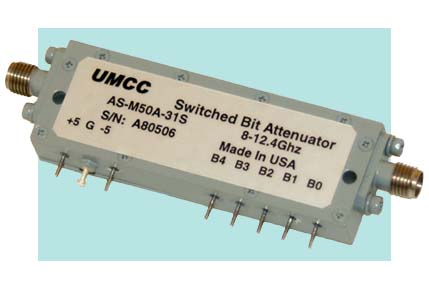
| Switched Bit Attenuators | |
|
|
|
|
Specifications are subject to
change without notice - Click on the product model number for Specifications-Sheet in PDF - Click on " |
|
|
Sales/Technical Contact Email: Sales@UMCC111.com |
UMCC offers this selection of pin-diode switch-Bit attenuators in wide bandwidths and high speed switching response time. Attenuators are available on special order to fit your specific application. All units are equipped with a high speed TTL driver. Each attenuation bit is controlled by one complementary (toggle) driver ckt and controlled via a single TTL/CMOS compatible command signal.. |
|
|
RF Circuit |
TTL Driver |
|
|
|
Specifications for Standard 5-Bit Models
|
Model
No. |
Frequency |
Insertion Loss (dB) Max |
VSWR Max |
Rise/Fall
Time (1) Max |
On/Off Time (2) Max |
Attenuation
Flatness (dB) Peak-Peak |
Outline Drawing |
||
|---|---|---|---|---|---|---|---|---|---|
| 10dB | 20dB | 31dB | |||||||
|
AS-H500-31S |
1 - 6 | 4.7 | 1.7:1 | 20 ns | 60 ns | 0.5 | 0.7 | 0.9 | Fig.1 |
|
AS-L500-31S |
2 - 8 | 5.5 | 1.7:1 | 15 ns | 50 ns | 0.6 | 0.8 | 1.0 | |
|
AS-M500-31S |
4 - 10 | 6.5 | 1.7:1 | 15 ns | 50 ns | 0.7 | 0.9 | 1.2 | |
|
1)
[ 10% RF Power to 90% RF Power (Rise Time) ] <> [ 90% RF Power to 10% RF
Power (Fall Time) ] |
|||||||||
| Common Specifications (All Standard 5-Bit Models): | ||
| 31dB | ||
| 5 | ||
| 1dB (B0=1dB, B1=2dB, B2=4dB, B3=8dB, B4=16dB) | ||
| 1- 10 dB | -/+ 0.75 dB Max | |
| >10- 31 dB | -/+ 1.25 dB Max | |
| -/+ 27 dBm CW/AVG <> 8W Peak, 1μS PW | ||
| 60dBc Min | ||
| TTL / Unit-Load / Floating-High (Logic "1") | ||
| Logic "0" = Bit "OFF" (Low Loss) | ||
| Logic "1" = Bit "ON" (Attenuation) | ||
| +5(-/+ 0.25)V @ 180mA Max | ||
| -5(-/+ 0.25)V @ 150mA Max | ||
| 50 Ω | ||
| - RF Input / Output | SMA (female), Removable | |
| - Supply and Control | Solder Pins | |
| Environmental Ratings: | ||
| - Operating | -55 degC to +95 degC | |
| - Storage | -60 degC to +110 degC | |
| Mil-STD-202F, Method 103B Condition B | ||
| Mil-STD-202F, Method 213B Condition B | ||
| Mil-STD-202F, Method 204D Condition B | ||
| Mil-STD-202F, Method 105C Condition B | ||
| Mil-STD-202F, Method 107D Condition B | ||
| Available Options: | |||
|
1) units with options
listed here may be subject to some specification
tradeoffs from the standard, consult factory 2) units with options listed here may be subject to lower or higher cost than the standard units. 3) Some options may not be available on all models, consult factory |
|||
| B1 [ J1 SMA(M) ] | - Other Attenuation Range and Steps (5-Bits Max , LSB>1dB) | ||
| B2 [ All SMA (M) ] | - Etc. | ||
|
|
|
|
|