|
|
|
|
|
| In-Phase (0deg) Power Dividers/Combiners: | ||||
|
In-Phase (0deg) Power Dividers/Combiners are passive components used for splitting a signal into two or more identical output signals (equal amplitude and phase), or to combine two or multiple signals into one output signal. Since Power Divider/Combiners are reciprocal devices, from now on in this article we refer to them as "Power Dividers" or simply "Dividers" whether or not they are used for splitting or combining purpose. For standard Power Dividers the condition for this summing or splitting function is to maintain a constant impedance of Zo (system impedance) at all ports over operating frequency boundaries of the device. Although Power Dividers are built for many diverse applications, the majority of the applications do require isolation among output ports. With exception of Resistive Power Dividers, all UMCC standard Power Dividers presented in this catalog are of the isolated type. The advantage of an isolated Divider is that the output at one port is not affected by an impedance mismatch at another output port, also the isolation would limit the power leakage from one output to another output port. |
||||
| Reactive Power Dividers: | ||||
| Reactive Power Dividers are built using various techniques in wide rage of frequencies. In general this class of Dividers are either of Lumped-Element design for low frequency applications from few kilohertz to about 3Ghz maximum, or of Distributed-Element design for frequencies from few hundred Megahertz and above. Although Reactive Dividers can be built without isolation among output ports, but in general isolation is an important characteristic of this class of Dividers. All UMCC Reactive Dividers do exhibit isolation among outputs. | ||||
|
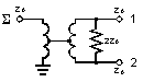
Lumped-Element 2-Way |
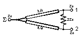
Distributed-Element 2-Way |
|||
|
|
|
|||
| -Power Splitting Analysis / Reactive Dividers: | ||||||||||||||||||||
| The net theoretical loss in an ideal Reactive Power Divider due to its splitting function is calculated from equation-1. In reality part of the power would be dissipated internally by power divider circuit elements such as transmission lines, Ferrite Cores, wires, connectors, etc. This additional loss is known as Insertion Loss of the device. Therefore the total actual loss would be the sum of the two loss (equation-2). | ||||||||||||||||||||
|
From Equation (1)
|
|||||||||||||||||||
| -Power Combining Analysis / Reactive Dividers: | |||
| Combining two or more signals with a Power Divider would result in a single signal appearing at the SUM port of the Divider. The characteristic of the signal at Sum port is directly related to the characteristic of each signal injected at inputs ports defined by signal frequency, amplitude, and phase. To further investigate the combined signal at SUM port of the Divider we would analyze a simple 2-Way Divider with two signals of Pa and Pb are combined. The two signals of Pa and Pb would have frequencies of Fa and Fb, amplitude of Aa and Ab, and phase of Өa and Өb consecutively. This analysis and argument can be further expanded to higher number of inputs with N signal combined with an N-Way Divider. | |||
|
Case 1- |
The two input signals of Pa and Pb are Non-Coherent (Fa≠Fb). In such a case the signal loss (Combine Loss) from either input port to the SUM port is 3dB for a 2-way divider. Or in case of an N-way Divider, and N non-coherent signals, the Combine Loss from either input to the SUM port is equal to the Split Loss and calculated with same equation we calculated the Split Loss earlier (equation-1): | ||
|
N Non-Coherent Signals / N-Way Divider / (Fa ≠ Fb ... ≠Fn) |
|||
|
|||
|
Case 2- |
The two inputs signals of Pa and Pb are Coherent (Fa=Fb), Phase and amplitude may or may not be equal. In such a case the insertion loss can be calculated from equation-5: | ||
|
2 Coherent Signals / 2-Way Divider / (Fa=Fb) |
|||
|
|||
| Two special cases can be driven from equation (5) | |||
| Case 2a- | The two Coherent signals Pa and Pb have equal amplitude and phase (Aa=Ab, Өa=Өb). From equation (5) we can conclude that Combine Loss would be equal to zero. No power would be absorbed internally by the Combiner | ||
| Case 2b- | The two Coherent signals Pa and Pb have equal amplitude but with 180 degree phase difference (Aa=Ab, |Өa-Өb|=180deg). From equation (5) we can conclude that Combine loss would be infinite. All the power would be absorbed internally by the Combiner. | ||
| Resistive Power Dividers: | |||||||||||||||
|
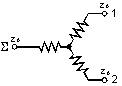
Resistive Dividers are built simply by using resistors for matching to Zo (system impedance) at each individual port. Dividers of this class are completely symmetrical and any port can be used as a SUM port. Since no frequency dependent elements (Reactive Elements) are used in construction of Resistive Dividers, the frequency band of a resistive divider is the widest from DC to any frequency higher. The high frequency limitation is due to the parasitic introduced by geometry, size, and construction of the dividing resistors, transmission lines, connectors, and other elements in the RF path. In contrary to Reactive Dividers, the Resistive Dividers do not exhibit isolation between outputs. Another disadvantage of Resistive Dividers is excess power absorption by the internal resistors. A 2-Way Resistive Divider has splitting loss of 6.02 dB (50% of power will be dissipated internally). The Split Loss of an N-Way Resistive Divider can be calculated from equation-7. %Power dissipation for an N-way Resistive Divider is predicted by equation-8. |
|||||||||||||||
|
N-Way Resistive Power Divider |
Resistive 2-Way |
||||||||||||||
|
|
||||||||||||||
|
N-Way Resistive Power Divider |
From Equation-7 and -8 |
||||||||||||||
|
|
||||||||||||||
|
|
|
|
|